Monday 29 August 2016

Globe Star Engineers(India) Pvt Ltd.


Company Introduction video of Globe Star Engineers(India)Pvt. Ltd.

Manufacturer of mechanical seal, rotary joint , Industrial Pumps and Pump Spare Parts,

Pump

Centrifugal Pump
Mud Pump
PP Pump
Other Industrial Pump
Pump Spare parts

for more info : www.globeseal.in & www.globeseal.com

Globe Star Engineers(India) Pvt Ltd.

Saturday 13 August 2016

How centrifugal pumps can be made more reliable….?


If you want to go purchase or investment in a centrifugal pump, you would expect it to trouble free functioning and maintain long time duration. Applying necessary improvements in varied areas such efficiency, reliability and containment helps in making these units more reliable. In addition to this, there are refinements comprising of remote telemetry evaluation, modern pump controls, with mechanical seal/Gland packing designs and variable speed drives. When these improvements are rightly followed, it generates potential for the reliable functioning.
However, this can only be achieved by following 3 basic steps right selection, installation and maintenance.


1.      Selection of Pump:   Seals, operating conditions and bearings are some of the key elements that prove beneficial in the selection of the pumps. It is imperative that centrifugal pumps should function at or near the set head (In meter) & flow rate (In m3/hour). The bearings of the pump is responsible for holding the rotating parts in their apt position and sized to bear the thrust and radial loads which is produced by the impeller.

There is one design that makes use of disks with or without radial vanes that help in the creation of frictional energy for the displacement of the fluid. Pressure gets balanced amid the disks and the bearings get to bear minimum load.

2.     Installation:  here are two main elements when it comes to the installation of centrifugal pumps (Both Alignment & Foundation). It has to be ensured that the anchor bolts are set in the concrete foundation in the correct fashion. The base of the foundation has to be chipped in order to permit the grout to follow. Base plates should be very clean, placed in its ideal place and should be leveled prior to the pouring of the grout.

Grout is responsible for bonding the base plate with the foundation and assists in the transmission of moments generated via driver, piping and pump to the foundation. Ensure that the weight of the foundation is three times the pump, pump and the coupling.
3.   Maintenance: A log on pump functioning can prove beneficial in identifying probable critical issues. A log like this comprise of changes in the lubrication, operation durations, maintenance procedures and packing alterations. It will prove beneficial for the periodic readings of flow, power input, suction and discharge pressure, noise levels, bearing temperature and fluid.
Wear rings offer right amount of prevention for the high pressured fluid to get leaked internally. In addition to this, it also offers a mean for minimizing hydraulic thrust of the pump. Because they make a difference in the performance of the pump, elevated clearance can elevate the power requirements by 5-7%.


Tuesday 2 August 2016

5 MAIN RULES OF PUMP PIPING


Many pumps are installed with inappropriate piping arrangements, resulting in premature pump failures, so many ways to Kill Your Pump.
If you were installing a pump in a new system, where would you turn for guidelines on proper pump piping arrangements?

·       By following 5 simple rules, you can avoid premature pump failure and related pump piping pitfalls :

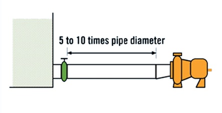
          1.    Keep suction pipe as short as possible.
Include a straight run pipe length equal to 5 to 10 times the pipe diameter between the pump inlet and any obstruction in the suction line.
Note: Obstructions include valves, elbows, "tees", and etc.
Keeping the suction piping short ensures that inlet pressure drop is as low as possible. The straight run pipe gives you a uniform velocity across the pipe diameter at pump inlet. 
Both are important to achieving optimal suction. 


2.    Pipe Diameter on suction side should be equal or one size larger than pump inlet.
Suction piping velocities should be limited to 7 to 8 feet per second or less.  

3.    Eliminate Elbows Mounted on OR Close to the inlet nozzle of the pump
Include 5 to 10 pipe diameters of straight run pipe between the pump inlet and elbow. This helps to eliminate "side loading" of the pump impeller and creates uniform pump axial bearing loading
4.    Eliminate potential for air entertainment in the suction piping.
Maintain adequate levels in supply tanks to eliminate vortices from forming and air entrapment.
Avoid high pockets in suction piping, which can trap air
Keep all pipe and fitting connections tight in suction vacuum conditions to prevent air from getting into the pump.
        
        5.    Ensure the piping arrangement does not cause strain on the pump         casing


       Pumps should never support the suction or discharge piping. Any stress        on the pump casing by the piping system greatly reduces pump life and        performance.

Friday 22 July 2016

WHY CENTRIFUGAL PUMP HAS LOW FLOW …?

Image result for centrifugal pump images

In the Industrial Industry, Centrifugal pump is most useful pump of the most of industry line. After using so much time of centrifugal pump, their media flow has been low in some reason,
So there are the most 8 reasons to solve this problem.
1
   .   Reversed Impeller Rotation: This may seem like a no-brainier, but it really is a common problem. When wiring the pump’s motor to power, it’s important to test which way the motor is turning first. “Bump Starting” the motor is a common practice where the motor is started without the pump hooked up to ensure proper rotation of the shaft. If the motor turns the wrong way, the impeller could potentially back off the shaft, causing serious damage to the internals.
  .     Clogged Suction: Make sure the suction pipe is free and clear of debris. Less flow into the pump will obviously yield less flow out of the pump.
3.    Worn impeller, wear ring, wear plate: If the vanes on the impeller are worn, the hydraulic capacity of the pump is reduced. Same with the wear ring and wear plate. When clearances open up due to wear, more re-circulation occurs inside the pump, reducing the pump’s flow.
4.    Excessive Clearances: If clearances are too wide for the type of fluid pumped, excessive slip will occur. Fluid will continue to recirculate inside the pump, yielding lower flow out of the pump.
5.    Debris in the impeller: If the eye of the impeller is plugged with debris, it removes the hydraulic capacity of the impeller to create an area of low pressure.
6.    Closed Discharge or Suction Valve: Again, this one seems really simple, but something that can be easily overlooked.
7.    Open Bypass Valve: Check to make sure the flow isn’t being diverted somewhere else through a bypass valve.
8.    Vortexing: This is more common with pumps in suction lift conditions, like a self-priming pump, or a vertical turbine. Make sure you’re meeting minimum submergence requirements to prevent vortex.

Wednesday 6 July 2016

MECHANICAL SEALS FOR WATER AND WASTEWATER PUMPS

Because mechanical shaft seal failures are the number one cause of pump downtime, the writer decided to dedicate this column to mechanical seal basics.
Years ago, most pump shafts were sealed using rings of soft packing, compressed by a packing gland, but this type of shaft seal required a fair amount of leakage just to lubricate the packing and keep it cool. Then came the development of the “mechanical seal,” which accomplishes the job of restraining product leakage around the pump shaft with two very flat surfaces (one stationary and one rotating).

Main elements of a Mechanical seals


Here is mentioned below, there are two seal face :
  • A set of (very flat) machined and lapped primary sealing faces: The very close (near) contact between these two flat mating surfaces, which are perpendicular to the shaft, minimizes leakage. Dissimilar materials are usually used for the faces, one hard and one softer, in order to prevent adhesion of the two faces. One of the faces is usually a non-galling material such as carbon-graphite. The other surface is usually a relatively hard material like silicon-carbide, or ceramic. However, when handling abrasive, two hard surfaces are normally used:
    • One face is held stationary in a housing
    • The other face is fixed to, and rotates with the shaft.
  • A set of secondary static seals, typically O-rings, wedges and/or V-rings.
    • One static seal, seals stationary component(s) to the housing
    • The other seal, seals the rotating component(s) to the shaft (it normally moves axially on the shaft or shaft sleeve)
  • A spring member to maintain face contact, such as a single spring, multiple springs or metal bellows.
  • Other mechanical seal hardware, which includes shaft sleeves, gland rings, collars, compression rings, and/or pins.

Mechanical seals require clean water, or other compatible liquid, for the lubrication of the seal faces. The faces in a typical mechanical seal are lubricated with a boundary layer of gas or liquid between the faces. Lubrication can be provided from the pumped liquid itself or from an external source, depending on system requirements.


Tuesday 28 June 2016

Troubleshooting Major Causes of Rotary Joint and Rotary Union Problems

Globe Star Engineers (India) Pvt. Ltd.


PRESENTS


“Troubleshooting Major Causes of Rotary Joint and Rotary Union Problems”


·        As mechanical devices with wear components, rotary joints are suspect to premature wear when not correctly installed. Below are the leading major happens of premature wear and how to limit the potential for early replacement of components due to improper installation.

·        Improper Piping

Improper piping that leads to piping strains. Piping strains lead to excessive force exertion on the body of the rotary joint or excessive guide wear with self-supported rotary joints. For rod-supported rotary joints, the support rods deflect under the excessive piping strain and that causes poor seal alignment.
Prevent piping strains by using proper flexible metal hoses, piping support, expansion joints or loops, and accurate rotary joint or rotary union installation.

·        Rotary Joint or Union Misalignment

Rotary joint or rotary union misalignment occurs when the centerline of the rotary joint components are not accurately aligned with the centerline of the journal.  Misalignment can cause interference with the rotary joint’s internal parts and significantly increases the wear rate of the sealing components. Symptoms of rotary joint and rotary union misalignment include:
·        Broken spring
·        Excessive key and key-way wear
·        Broken horizontal siphon pipes
·        Broken journal flange bolts
·        Broken nipple flange studs
·        Flexible metal hose failures
·        Broken carbon guides
Prevent misalignment by accurately installing the rotary joint and supporting equipment.  Evenly torque journal flange and nipple flange fasteners.  Bent support rods or poorly aligned mounting brackets are common causes for misalignment as well.

·        Lack of/Improper Torque Restraint

Lack of a torque restraint or an improper torque restraint increases the radial forces that are applied to self-supporting rotary joints. Using flexible hoses as a torque restraint causes high radial loads to be applied to the rotary joint.  An overly restrictive torque restraint can cause excessively high forces as well.  A properly designed torque restraint allows the rotary joint or rotary union to move axially and radially while preventing rotation.
·        For more information :

Visit our website: http://globeseal.in